Printable Hydraulics
Printable Hydraulics: A new method for fabricating force-transmission elements within robots
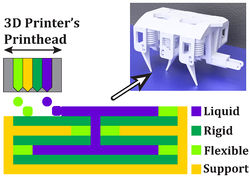
Multi-material additive-manufacturing techniques offer a compelling alternative to conventional rigid and soft robot fabrication techniques, allowing materials with widely varying mechanical properties to be placed at arbitrary locations within a structure, and enabling design iterations to be rapidly fabricated with trivial effort. This capability enables complex composite materials with new bulk properties, and in contrast to virtually all other fabrication techniques, the incremental costs of additional design complexity when using additive manufacturing are zero. We show how commercial multi-material 3D printers can be adapted to co-fabricate solids and fluids within the same 3D-printed structure, demonstrating a new capability for transmitting force within 3D-printed assemblies: Printable Hydraulics.
Publications:
-
Robert MacCurdy, Robert Katzschmann, Youbin Kim, Daniela
Rus
- Printable
Hydraulics: A Method for Fabricating Robots by 3D
Co-Printing Solids and Liquids 2016 IEEE
International Conference on
Robotics and Automation (ICRA)
Design Files:
Videos:
Automated assembly of integrated robotic structures
 |
 |
This method, based on inkjet deposition of photopolymers and
non-polymerizing fluids, can achieve resolutions better than 100μm,
allowing the fabrication of complex channels for fluid routing and
capillary structures for selectively distributing hydraulic pressure to
regions of the assembly with precisely graded elasticity, enabling
prescribed movements in response to pressure changes. Control of
complex composite assemblies fabricated in this manner is simplified
because the working fluid is incompressible; because the solid and
fluid regions are fabricated together, there is no need to purge air
bubbles or remove support material. The key idea of this approach to
robot fabrication is to automate the assembly of complete robotic
structures. By reducing or eliminating assembly steps, this method
breaks the connection between design complexity and fabrication
complexity, allowing complex designs to be fabricated with trivial
effort.
Basic Transducer Unit: the Bellows
 |
 |
The achievable feature sizes of drop-on-demand inkjet printers are too
coarse to print sliding seals; they would leak. As a result,
conventional piston designs are not practical. An alternative design
using a bellows avoids the need to have seals entirely. As the pressure
inside the bellows increases the material deforms and the bellows
extends. This deformation can be estimated using finite element
modeling tools to ensure that the stress and strain in the printed
material does not exceed allowable limits. The bellows design is
inherently modular: if greater actuator extension is required
additional folds can be added, and if larger force is required (for a
given input fluid pressure) the cross-section of the bellows can be
increased.
Fabricating a robot in a single step
 |
 |
 |
 |
We designed a tripod-gait hexapod with a single rotational degree of
freedom (DOF), illustrated above. All mechanical components
of this robot are printed in a single step with no assembly required.
This robot weighs 690 g, is 14 cm long, 9 cm wide and 7 cm tall. The
legs are designed with a neutral position that inclines their major
axis 60 degrees above the floor and each leg is actuated by a bellows,
causing the leg to rotate 10 degrees in either
direction, relative to this neutral position. Three of the legs are
inclined toward the front of the robot (bank A) and three are inclined
toward the rear (bank B). Each driven bellows is internally connected
to a corresponding
driving bellows via a fluid channel that runs through the robot’s body;
the fluid in each driving/driven bellows pair is isolated from the
other bellows. The three driving bellows from bank A are kinematically
linked and attached to a crankshaft via a connecting rod. The bellows
from bank B are similarly connected to a separate section of the
crankshaft that is 90 degrees out of phase. The crankshaft is turned at
30 RPM by a single geared DC motor consuming approximately 2 W (Pololu
#3070), yielding a locomotion speed of 0.125 body-lengths per second.
This arrangement moves the legs from the two banks 90 degrees out of
phase with each other, enabling forward or backward locomotion without
an additional DOF at each leg, and does not require the feet to slide
on the floor.
Applications to Soft-Robotics
 |
 |
 |
 |
Soft robots are usually fabricated via cast elastomers, and although
casting soft robots is often faster than assembling conventional rigid
robots, the mold-making process can be time consuming, and embedding
multiple materials within a cast object via overmolding adds
complexity. Additionally, producing complex, graded materials via
casting is difficult. Additive manufacturing, combined with the printed
hydraulics approach, provides an alternative fabrication method for
soft robotics that is automated, flexible, and enables geometries that
are infeasible with other production methods. As a demonstration of the
utility of printable hydraulics to the soft robotics community, we
designed and printed a two-finger soft gripper, shown above. The design
process required four iterations. Each iteration required 3.5 hours to
print and a short time to evaluate the performance of the part. This
method is faster and more automated than soft robot fabrication
approaches that rely on casting materials into molds. Additionally, the
final gripper design incorporates thin channels and internal fluid
routing that would be difficult to achieve via casting.
Printed Gear Pumps
 |
Gear pumps are low-flow, high-pressure devices, are commonly employed
in hydraulic systems, and are capable of
producing continuous flow. We designed and printed a gear pump to
present an alternative to the bellows pump, which
produces only reciprocating flow. These pumps employ a pair of enmeshed
counter-rotating teeth enclosed in a tight-fitting housing. Fluid
trapped between the teeth and the housing is moved from the
low-pressure port to the high pressure port, and is prevented from
moving back by the meshed teeth near the center of the pump. The gears
have a pitch diameter of 17.5 mm, an outer diameter of 19.6 mm, a
modulus of 1.25, and a gear height of 8 mm. We followed the common
practice of using involute gears with a 20 degree pressure angle.